Calibration and Transformation
Field-of-view Calibration
Calibration establishes the relationship between real-world point coordinates and image pixels. A simple calibration model computes faster, a repeatable part position is easier to locate. |
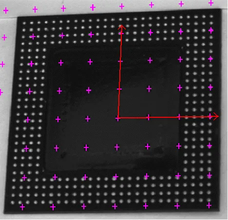
|
The Raw sensor coordinate system starts from upper left and extends rightwards and downwards. |
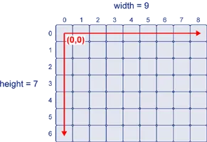
|
The Centered sensor coordinate system starts at the center ([width-1]/2, [height-1]/2 in the Raw system) and extends rightwards and upwards. |

|
The real world 3D coordinates are defined in a 2D reference frame tied to a reference plane. The origin and direction of the axis are normally aligned with major features of the inspected parts. |
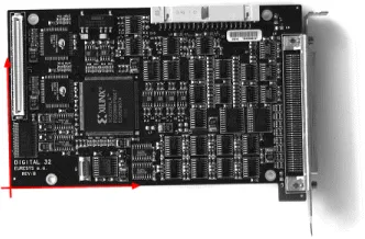
|
Before World-to-Sensor Transform
Before converting from world to sensor coordinates, sources of distortion should be eliminated:
adjust sweep frequency or scanning speed to avoid non-square pixels.
adjust optical alignment to minimize perspective effect. The field of view should be parallel to the sensor plane.
use long focal distances and good quality lenses to minimize Optical distortion.
use appropriate scale factor based on lens magnification, observation distance and focusing.
minimize skew and translation effects by secure fixtures, and part-movement / acquisition-triggering synchronization.
Effects of World-to-Sensor Transform
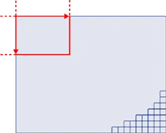
No calibration. World and sensor coordinates are identical. |
|
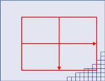
Translated calibration: The coordinate origin can be moved. World coordinates correspond to pixel units. |
|
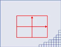
Isotropic scaling (square pixels). A scale factor converts pixel values to physical measurements. |
|
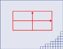
Anisotropic scaling (non-square pixels). Uses two scale factors with pixel aspect ratio (X /Y ) in the range [-4/3, -3/4] (or [3/4, 4/3]). Pixels are always displayed as square, so the image appears stretched. |
|
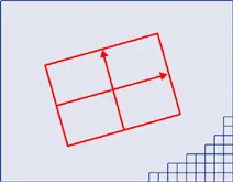
Scaled and skewed (square pixels). Real-world axis aligns with rotated inspected part using translation, rotation and scaling. |
|
Scaled and skewed (non-square pixels). Distortion is apparent. Occurs when camera scan speed does not match pixel spacing. |
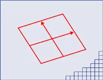
|
Perspective distortion causes further away objects to look smaller; lines remain straight but angles are not preserved. |
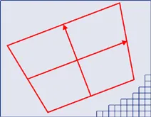
|
Optical distortion causes cushion or barrel appearance of rectangles. |
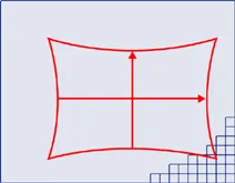
|
Combined distortions result in a complex, non linear, transform from real-world to sensor spaces. |
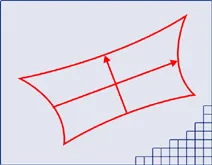
|