Photometric Stereo
Photometric Stereo is a technique used to estimate the normals at the surface of an object.
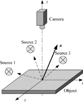
Photometric stereo setup
Source: https://www.researchgate.net/figure/Principle-of-photometric-stereo_fig7_222422584
It takes at least 3 images of the same object taken under different known light directions.
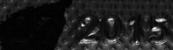
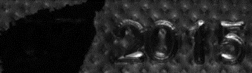
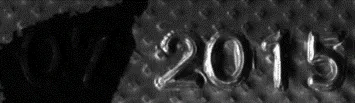
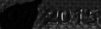
Inputs: images with different light directions
It produces an image containing the fraction of light reflected (called albedo) and the normal of the surface at each pixel.
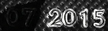 Albedos.
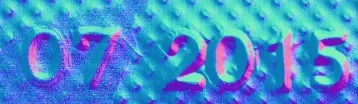 Normals.
The normals are processed to compute gradients and curvatures, allowing to easily see bumps and holes. You can also integrate the normals to compute the height map.
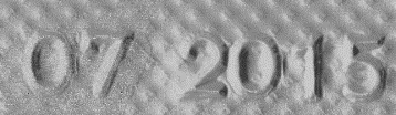 Gradients X.
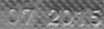 Gradients Y.
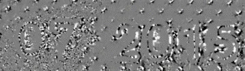 Gaussian curvatures.
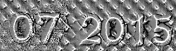 Mean curvatures.
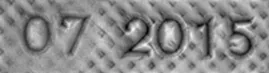 Height map.
Process
You can use the object EPhotometricStereoImager .NET Python in a 4-step process:
Calibrate the setup from a sphere or from predefined angles (once per setup).
Perform the photometric stereo computation on the object images.
Retrieve the results.
Use and apply the eVision tools on the results.
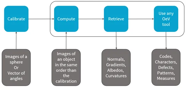
Photometric stereo process
See also
Calibration
You can perform the calibration either:
By setting the calibration angles.
By computing the calibration angles from images of a (hemi)sphere.
Azimuth and Elevation
To define a light direction, two angles are necessary, the
azimuthand theelevation.When facing the image, the X-axis points right, Y points top and Z points towards the camera.
The
azimuthangles are oriented trigonometrically around the Z-axis.A light source on the right of the image has an azimuth of \(0°\).
A light source on the top of the image has an azimuth of \(90°\).
The
elevationis the angle formed by the base plane and the light source.A light source on the horizon has an elevation of \(0°\).
A light source on the camera has an elevation of \(90°\).
Code Snippet
The following code snippet shows how to perform the calibration from a (hemi)sphere.
#include <eVision/Easy3D/EPhotometricStereoImager.h>
using namespace eVision;
using namespace eVision::Easy3D;

EPhotometricStereoImager photometricStereo;

std::vector<EImageBW8> calibrationImages;
// Load calibration images (Todo)
std::vector<EROIBW8> calibrationROIs;
// Set the calibration ROIs (Todo)

// Calibrate
float score = photometricStereo.CalibrateFromSphere(calibrationROIs);

std::vector<EImageBW8> objectImages;
// Load object images in the same order than the calibration images/angles (Todo)

std::vector<EROIBW8> objectROIs;
// Set the object ROIs (Todo)

// Compute
photometricStereo.Compute(objectROIs);

// Retrieve the results
EImageC24 normals = photometricStereo.GetNormals();
EImageBW8 albedos = photometricStereo.GetAlbedos(Easy3D::EPhotometricStereoContrast_HighContrast);
EImageBW8 gradientsX = photometricStereo.GetGradientsX();
EImageBW8 gradientsY = photometricStereo.GetGradientsY();
EImageBW8 gaussianCurvatures = photometricStereo.ComputeGaussianCurvatures(Easy3D::EPhotometricStereoContrast_HighContrast);
EImageBW8 meanCurvatures = photometricStereo.ComputeMeanCurvatures(Easy3D::EPhotometricStereoContrast_HighContrast);
EZMap8 heightMap = photometricStereo.ComputeHeightMap();
using eVision;
using eVision.Easy3D;
EPhotometricStereoImager photometricStereo = new EPhotometricStereoImager();

EImageBW8[] calibrationImages = new EImageBW8[4];
// Load calibration images (Todo)
EROIBW8[] calibrationROIs = new EROIBW8[4];
// Set the calibration ROIs (Todo)

// Calibrate
float score = photometricStereo.CalibrateFromSphere(calibrationROIs);

EImageBW8[] objectImages = new EImageBW8[4];
// Load object images in the same order than the calibration images/angles (Todo)

EROIBW8[] objectROIs = new EROIBW8[4];
// Set the object ROIs (Todo)

// Compute
photometricStereo.Compute(objectROIs);

// Retrieve the results
EImageC24 normals = photometricStereo.Normals;
EImageBW8 albedos = photometricStereo.GetAlbedos(EPhotometricStereoContrast.HighContrast);
EImageBW8 gradientsX = photometricStereo.GradientsX;
EImageBW8 gradientsY = photometricStereo.GradientsY;
EImageBW8 gaussianCurvatures = photometricStereo.ComputeGaussianCurvatures(EPhotometricStereoContrast.HighContrast);
EImageBW8 meanCurvatures = photometricStereo.ComputeMeanCurvatures(EPhotometricStereoContrast.HighContrast);
EZMap8 heightMap = photometricStereo.ComputeHeightMap();
import eVision
from eVision import Easy3D
from typing import cast
photometric_stereo = Easy3D.EPhotometricStereoImager()

calibration_images = [eVision.EImageBW8(), eVision.EImageBW8(),
    eVision.EImageBW8(), eVision.EImageBW8()]
# Load calibration images (Todo)
calibration_rois: list[eVision.EROIBW8 | None] = [eVision.EROIBW8(), eVision.EROIBW8(),
    eVision.EROIBW8(), eVision.EROIBW8()]
# Set the calibration ROIs (Todo)

# Calibrate
score = photometric_stereo.CalibrateFromSphere(calibration_rois)

object_images = [eVision.EImageBW8(), eVision.EImageBW8(),
    eVision.EImageBW8(), eVision.EImageBW8()]
# Load object images in the same order than the calibration images/angles (Todo)

object_rois: list[eVision.EROIBW8 | None] = [eVision.EROIBW8(), eVision.EROIBW8(),
    eVision.EROIBW8(), eVision.EROIBW8()]
# Set the object ROIs (Todo)

# Compute
photometric_stereo.Compute(object_rois)

# Retrieve the results
normals = photometric_stereo.Normals
albedos = photometric_stereo.GetAlbedos(Easy3D.EPhotometricStereoContrast.HighContrast)
gradientsX = photometric_stereo.GradientsX
gradientsY = photometric_stereo.GradientsY
gaussian_curvatures = photometric_stereo.ComputeGaussianCurvatures(Easy3D.EPhotometricStereoContrast.HighContrast)
mean_curvatures = photometric_stereo.ComputeMeanCurvatures(Easy3D.EPhotometricStereoContrast.HighContrast)
height_map = photometric_stereo.ComputeHeightMap()
If the sphere is not detected, the calibration fails and generates an
EException.NET Python (EError.NET PythonEError_SphereDetectionFailed.NET Python).
In that case, you can pass the position of the circle to the method:
ECircle circle;

// Define circle

photometricStereo.CalibrateFromSphere(calibrationROIs, circle);
ECircle circle = new ECircle();

// Define circle

photometricStereo.CalibrateFromSphere(calibrationROIs, circle);
circle = ECircle()

# Define circle

photometricStereo.CalibrateFromSphere(calibrationROIs, circle)
The method returns a score that indicates the reliability of the calibration.
The higher the value, the better the calibration.
The score range is \([0, 1]\).
The scores above 0.75 are considered as good.
The scores below 0.50 are considered as bad.
The scores in between are considered as acceptable.
The method never fails. A bad score does not mean that you will not get good results on your images. It means that, if you do not, it is probably due to the calibration.
The score is composed of 2 factors:
The lambertian (matte) of your sphere (the more lambertian the better).
The plausibility of the detected light directions.
The following figure shows the scores for 2 examples.
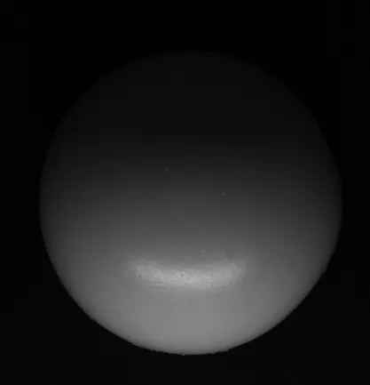 High reflection sphere (score 0.70).
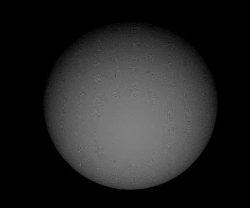 Perfectly lambertian sphere (score 0.96).
You can also directly set the calibration angles and retrieve them.
Use Easy::SetAngleUnit .NET Python to define the angle unit.
Easy::SetAngleUnit(EAngleUnit_Degrees);

std::vector<float> azimuths, elevations;

// Define the values of the angles

photometricStereo.SetCalibrationAngles(azimuths, elevations);
Easy.AngleUnit = EAngleUnit.Degrees;

float[] azimuths = new float[4], elevations = new float[4];

// Define the values of the angles

photometricStereo.SetCalibrationAngles(azimuths, elevations);
Easy.AngleUnit = EAngleUnit.Degrees

azimuths = []
elevations = []

# Define the values of the angles

photometricStereo.SetCalibrationAngles(azimuths, elevations)
Computation and Results
Computation
Once the calibration is done, you can perform the photometric stereo computation on the object images using
EPhotometricStereoImager::Compute().NET PythonThe computation time is proportional to the number of pixels in the image. To reduce this time, you can:
The following table shows the computation time in different configurations (when computing albedos, mean and Gaussian curvatures with high contrast, see below).
Number of lights |
Image size |
Number of threads |
Computation time (ms) |
||
|---|---|---|---|---|---|
4 |
4096 × 3072 |
1 |
479 |
⤸ / 1.4 |
⤸ / 11 |
4 |
337 |
||||
4 |
1024 × 768 |
1 |
52 |
⤸ / 1.2 |
|
4 |
42 |
Retrieving Results
Use the getter methods (like
EPhotometricStereoImager::GetGradientsX.NET Python,EPhotometricStereoImager::GetNormals.NET Python…) orCompute...ofEPhotometricStereoImager.NET Python to retrieve your results.The
normalsEImageC24.NET Python represents the \((x, y, z)\) normals of the surface at each pixel.A RGB pixel intensity of \((0, 128, 255)\) corresponds to an \((x, y, z)\) normal of \((-1, 0, 1)\)
The
albedosEImageBW8.NET Python represents the fraction of light reflected at each pixel.Compared to the input image, the albedo is independent of the lighting direction and intensity.
The albedos are normalized to the full image range.
The
gradientsXand thegradientsYEImageBW8.NET Python represent the gradients of the surface along the X- and Y-axis.The gradients are clipped to \(\pm 3.715\) before being mapped to the full image range.
The
gaussianCurvaturesand themeanCurvaturesEImageBW8.NET Python represent the local curvature of the surface at each pixel.The Gaussian curvatures are important when the curvature of the object is big in 2 orthogonal directions.
The mean curvatures only need an important change in 1 direction.
You can think of the Gaussian and the mean curvatures as a corner detector and an edge detector.
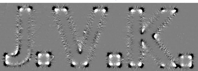 Gaussian curvature (highlights corners).
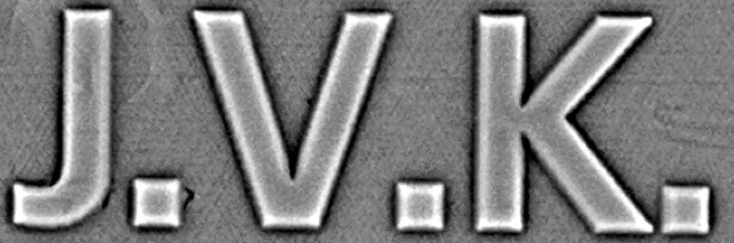 Mean curvature (highlights edges).
Each pixel of the height map
EZMap8.NET Python represents the height of the object.The pixel furthest from the camera has a height of 1.
The pixel closest to the camera has a height of 255.
Most of the computations are done in the method EPhotometricStereoImager::Compute .NET Python, however:
The last computations required for the curvatures and the height map are only performed when retrieving them to avoid computing them unnecessarily.
This is why these methods are named
ComputeXXXinstead ofGetXXX.Intermediary results common to the mean and the Gaussian curvatures are cached to avoid computing them several times.
Albedos, mean and Gaussian curvatures are intrinsically floating point images. To convert them to
EImageBW8.NET Python, you can choose between several arguments:EPhotometricStereoContrast_HighContrast.NET Python to ignore outliers and produce images with a high contrast.EPhotometricStereoContrast_FullRange.NET Python to produce images where no data is ignored.EPhotometricStereoContrast_FixedRange.NET Python to produce images where the range is specified using an additional argument. This is especially useful when processing several different objects with a fixed threshold.
Tuning Blurring Before Computing Curvatures
To improve results, some Gaussian blurring is applied before the computation of the curvatures:
By default, the standard derivation of the kernel is set to 1.
This is not always the optimal value. For example, with our sample braille images, a kernel with a sigma of 3 works better to detect the circles on the Gaussian curvature image.
Use the property
GaussianBlurSigmaofEPhotometricStereoImager.NET Python to adjust the standard derivation of the blur.
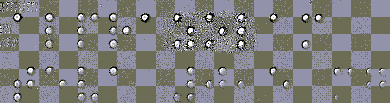 Gaussian curvature with sigma = 1.
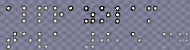 Gaussian curvature with sigma = 3.
Processing the Results with eVision Tools
As the computation results are EImageBW8 .NET Python, you can process them with the various tools of eVision.
Here are some examples:
Reading an embossed code with EasyBarCode, EasyMatrixCode and EasyQRCode.
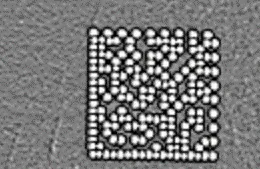 Mean curvatures of an engraved matrix code.
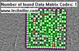 EasyMatrixCode2 reading.
Reading an engraved text with EasyOCR2.

EasyOCR2 reading on the mean curvatures
Finding patterns on embossed surfaces with EasyFind, EasyMatch and EasyObject.
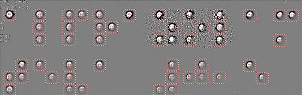
EasyFind results on the Gaussian curvatures to detect braille characters
Measuring shapes with EasyGauge.
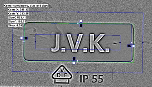
Rectangle measurement with EasyGauge on the mean curvatures
Finding defects in objects with EasySegment.
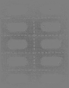 Gaussian curvatures of a blister pack with 3 holes.
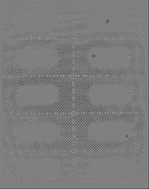 EasySegment supervised potential results.
Optimizing Your Setup
Photometric stereo is based on two main assumptions:
The light has the same intensity and direction for each pixel of the image.
The object is mostly matte and not too specular.
Matte surfaces send back light in all directions (wood is a good example).
Specular surfaces send all the light in a single direction (mirrors are a good example).
While these conditions are never met in practice, deviating too much from them often causes poor results.
Uniformity of the Lights
Ideally, all pixels of interest should be lit with the same intensity and from the same direction.
To achieve this:
We recommend using bar lights or ring lights designed for photometric stereo.
They should be larger than the objects you want to acquire.
Note
The sample images were taken with a bar light of around 15cm in length and a ring light of around 15cm of diameter. Both gave similar results.
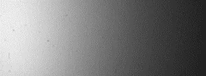
The image of the sheet of paper is whiter on the left when, ideally, it should be uniformly white.
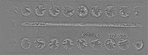
If you are interested in curvatures, this does not prevent acquiring good images, while the albedos and normals images are more affected by this.
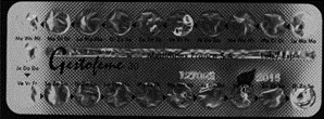
In the mean curvature and albedo image above, you see artifacts on the left and on the right of the object, while not at the top and the bottom. This is because the object is large and not so high, so the lights are mostly uniform on the object when coming from the top or bottom but not when coming from left or right.
It can be alleviated by using Flat Images, as shown in the next section but it does not solve the problem completely.
Hint
In practice, you can measure the uniformity of your lights by acquiring an image of a matte sheet of paper.
Specularity of the Object
Photometric Stereo works better on matte surfaces as the reflection of the source light by the object causes artifacts. Please note however that a little reflection is not necessarily a problem. This is something to keep in mind when analyzing results.
This also applies to the calibration hemisphere. The current calibration algorithm is designed to handle a bit of reflection but too much of it induces calibration errors. Nevertheless, though there is reflection in our sample images, the calibration still works on them.
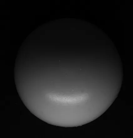
Example calibration hemisphere with acceptable specularity.
Hint
We recommend using a wooden hemisphere or one covered in matte paint.
Improving the Results
Using a Dark Image to Account for Ambient Lighting
In order to apply photometric stereo, we assume that each image is lit from a single light source.
This assumption is not valid if the setup is exposed to (non-negligible) ambient lighting.
To handle this issue, the
EPhotometricStereoImager.NET Python provides anEImageBW8.NET Python dark image to the methodsEPhotometricStereoImager::CalibrateFromSphere.NET Python andEPhotometricStereoImager::Compute.NET Python.This dark image is an image of the object under ambient light only (all setup lights are off).
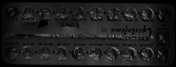
The dark image
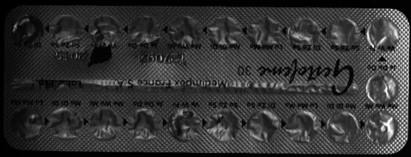 Raw object image.
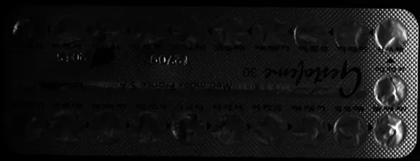 Object image after dark image correction.
Using Flat Images to Correct Non-Uniform Lighting
In order to apply photometric stereo, we assume that each image is lit from a uniform light source.
This means that each pixel is lit by the same quantity of light.
This assumption is not valid in physical setups using leds, where the part of the image closest to the leds receives more light.
To handle this issue, the
EPhotometricStereoImager.NET Python provides a method to register a flat image used by the methodEPhotometricStereoImager::Compute.NET Python.
This flat image is an image of a uniform background taken in the same lighting configuration.
#include <eVision/Easy3D/EPhotometricStereoImager.h>
using namespace eVision;
using namespace eVision::Easy3D;

EPhotometricStereoImager photometricStereo;
// calibrate imager or sets its angles (Todo)

// Load flat images in the same order than the calibration images/angles (Todo)

std::vector<EROIBW8> flatROIs;
// Set the flat images ROIs (Todo)

// Configure flat images, this could optionally be done with a dark image as well
photometricStereo.ConfigureNonUniformLightingCorrection(flatROIs);

std::vector<EROIBW8> objectROIs;
// Set the object ROIs (Todo)

// Perform one or more computations, each will use the flat images (Todo)
photometricStereo.Compute(objectROIs);

// Optional: non uniform lighting correction could be disabled or (re-)enabled
// using SetEnableNonUniformLightingCorrection
using eVision;
using eVision.Easy3D;
EPhotometricStereoImager photometricStereo = new EPhotometricStereoImager();
// calibrate imager or sets its angles (Todo)

// Load flat images in the same order than the calibration images/angles (Todo)

EROIBW8[] flatROIs = new EROIBW8[4];
// Set the flat images ROIs (Todo)

// Configure flat images, this could optionally be done with a dark image as well
photometricStereo.ConfigureNonUniformLightingCorrection(flatROIs);

EROIBW8[] objectROIs = new EROIBW8[4];
// Set the object ROIs (Todo)

// Perform one or more computations, each will use the flat images (Todo)
photometricStereo.Compute(objectROIs);

// Optional: non uniform lighting correction could be disabled or (re-)enabled
// using SetEnableNonUniformLightingCorrection
import eVision
from eVision import Easy3D
photometric_stereo = Easy3D.EPhotometricStereoImager()
# calibrate imager or sets its angles (Todo)

# Load flat images in the same order than the calibration images/angles (Todo)

flat_rois: list[eVision.EROIBW8 | None] = [eVision.EROIBW8(), eVision.EROIBW8(),
    eVision.EROIBW8(), eVision.EROIBW8()]
# Set the flat images ROIs (Todo)

# Configure flat images, this could optionally be done with a dark image as well
photometric_stereo.ConfigureNonUniformLightingCorrection(flat_rois)

object_rois: list[eVision.EROIBW8 | None] = [eVision.EROIBW8(), eVision.EROIBW8(),
    eVision.EROIBW8(), eVision.EROIBW8()]
# Set the object ROIs (Todo)

# Perform one or more computations, each will use the flat images (Todo)
photometric_stereo.Compute(object_rois)

# Optional: non uniform lighting correction could be disabled or (re-)enabled
# using SetEnableNonUniformLightingCorrection
The following example illustrates the effect of a non-uniform lighting correction on the object images.
The proximity of the light source generates a lighting effect on the left of the image that is visible on both the flat and the raw images.
This effect is corrected on the last image, where the brightest pixels are those oriented towards the surface.
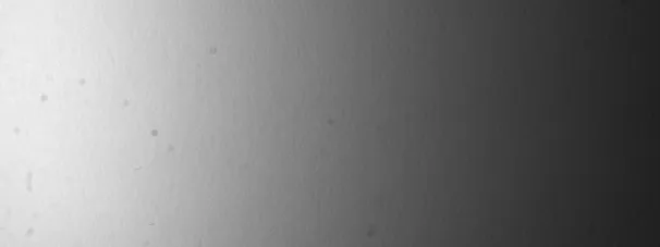
The flat image
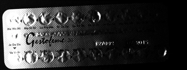 Raw object image.
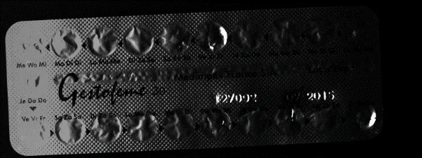 Object image after flat image correction.
The following examples illustrate the effects of a non-uniform lighting correction on 2 albedos images.
The corrected albedos show less burning on the extremities of the images.
 Raw albedo (image 1).
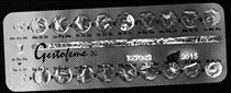 Corrected albedo (image 1).
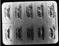 Raw albedo (image 2).
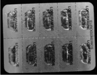 Corrected albedo (image 2).
The following examples illustrate the effects of a non-uniform lighting correction on a normals images.
The normals fields is more uniform.
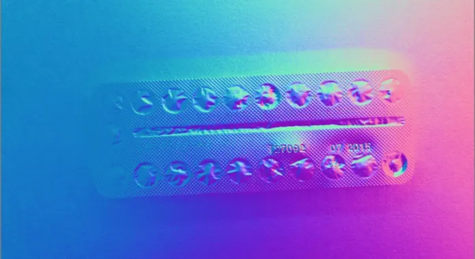 Raw normals image.
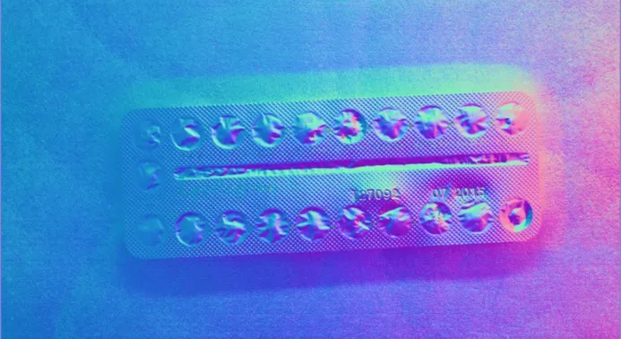 Normals image after flat image correction.
Effect of the Distance Between Lights and Object
There is a tradeoff in the distance between the light and the object (that is the elevation angle).
When the elevation angle is high, the lighting is more uniform. This means that:
The “burning” effects visible on some images is less important.
The shadows are also less of a problem.
When the lighting source is close, the lighting directions are more diverse. This means that:
The quantity of information used to build the photometric stereo is higher.
Hint
We recommend using elevation angles between 30 and 70°. We achieve our best results around 40°.