Easy3DMatch - 3D Alignment and Comparison
Easy3DMatch allows you to:
Align a scanned object with another scan or with a reference mesh.
The Easy3DMatch tool features alignment functions to find the exact pose (position and orientation) of acquired 3D objects using a reference model.
You can specify this model as a reference point cloud or as a 3D mesh from CAD software (using the
stlfile format).
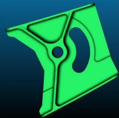 CAD model.
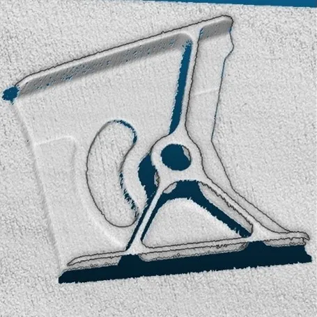 Sample point cloud.
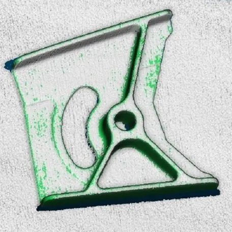 Model and sample aligned.
3D models courtesy of Direct Dimensions.
Compare an aligned scan with a reference model or mesh:
Compute the local distances between 3D scans and a golden sample or a reference mesh.
Detect anomalies such as misplaced features, geometric distortions, gaps and bumps.
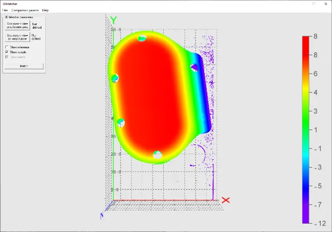 Reference.
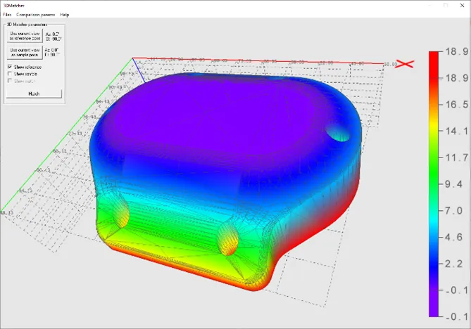 Sample.
3D CAD models courtesy of Direct Dimensions.
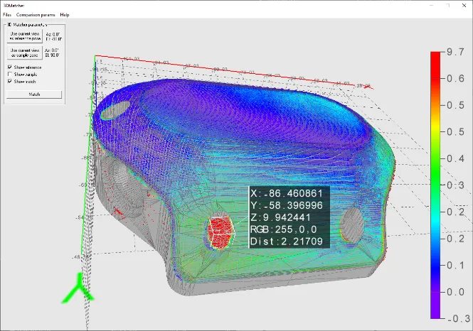
Result of the comparison
Workflow
Load a reference as:
A mesh (define its viewpoints)
A point cloud (with one viewpoint)
A ZMap
Load a sample, either as:
A point cloud (with one viewpoint)
A ZMap
Perform alignment and/or matching:
Optionally, align the sample and get its
E3DAlignment.NET Python with respect to the reference (E3DAligner.NET Python).Optionally, compare the sample to the reference by defining ROIs as
E3DBox.NET Python (E3DComparer.NET Python).Align the sample and compare it directly to the reference by defining ROIs as an
ERegion.NET Python (E3DMatcher.NET Python).
Use the transformation from sample to model to locate the sample and/or process the detected
E3DAnomaly.NET Python.
Alignment
Base Case
Use the class E3DAligner .NET Python to load a reference and a sample and to find the transformation from the sample to the reference.
The first step is to set the reference using the method
SetReference.In addition to the mesh or the cloud, this method also takes one or several
E3DPlaneor azimuth and elevation angles (see Calibration for a definition of the azimuth and the elevation).The angles are used to compute the plane and are just an easier way to specify it.
The goal of the plane is to specify the face(s) of the object that can be visible on the sample.
You must do this only once for the reference and once for the sample(s), assuming they are all taken with the same scanner.
Here is an illustration of the process:

View of the CAD
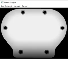
Bottom face, corresponding to the plane of the normal \((0, 0, -1)\) and equation \(z = 15\) or an azimuth of \(0°\) and an elevation of \(-90°\)
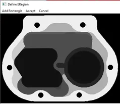
Top face of the object, corresponding to the plane of the normal \((0, 0, 1)\) and equation \(z = -15\) or an azimuth of \(0°\) and an elevation of \(90°\).
Call the method
E3DAligner::Align.NET Python with a point cloud or a zmap and get an objectE3DAlignment.NET Python that contains:The pose, an
E3DTransformMatrix.NET Python mapping the sample to the reference.The error, indicating the quality of the matching.
The index of the reference pose that was matched. This is useful when several poses are defined (in the example above, there are 2 poses defined).
Defining a reprojection plane to improve the results
Ideally, the sample (and the point cloud or the ZMap used as reference) should be aligned on the viewpoint. This is however not always true, for example when the scanner does not lay on top of the object. In these cases, the user may specify the plane on which the object lays, either by giving an E3DPlane .NET Python or a flat scan on which only the plane is visible.
In both cases, the plane normal must have the correct orientation (pointing upwards or downwards), that is if the plane is above the normal (\(z_\text{object} > z_\text{plane}\)), the \(z\) coordinate of the normal should be positive. This is specified either directly in the E3DPlane .NET Python or by a boolean argument objectAbovePlane when giving a flat scan.
See also
Code snippets:
Comparison
Base Case
Use the class E3DComparer .NET Python to load a reference and an already aligned sample (for example by using E3DAligner .NET Python) and to find the distance map between both as well as anomalies.
To use the
E3DComparer.NET Python:Use the method
E3DComparer::SetMeshReference.NET Python orE3DComparer::SetPointCloudReference.NET Python to specify the reference with either anEMesh.NET Python or anEPointCloud.NET Python.Set the options of the comparison (ROIs, mode and thresholds).
Call the method
E3DComparer::Compare.NET Python with the sampleEPointCloud.NET Python.Use
E3DComparer::ComputesAnomalies.NET Python to retrieve the list ofE3DAnomaly.NET Python.Use
E3DComparer::GetComparisonPointCloud.NET Python to retrieve theEPointCloud.NET Python containing the distances.
An
E3DAnomaly.NET Python represents a specific area in which the discrepancies between the sample and the reference are important. They are represented by:An
EPointCloud.NET Python containing all the points of the anomaly and their distance to the sample.The area of the anomaly.
Its center of gravity.
A bounding box around the anomaly.
Note
The E3DAnomaly .NET Python represents points on the reference (except on E3DComparer::SetNoExtraMaterial .NET Python regions and when the distance mode is set to EComparisonDistanceMode_Euclidean_Advanced .NET Python or EComparisonDistanceMode_Normals_Advanced .NET Python).
Use
E3DComparer::GetComparisonPointCloud.NET Python to retrieve anEPointCloud.NET Python containing distance and/or colors that represent the distance to the sample or the reference for each of these points.SetROIandSetDontCareThe class
E3DComparer.NET Python can perform the comparison on only a subset of the object. This has two benefits: it is faster and it allows to ignore false-positives when detecting anomalies.Use
E3DComparer::SetROI.NET Python with a vector ofE3DBox.NET Python to define the zones on which to perform a comparison.Use
E3DComparer::SetDontCare.NET Python to specify areas that are excluded from the comparison.A point belonging to
E3DComparer::SetROI.NET Python andE3DComparer::SetDontCare.NET Python boxes is not compared. By default, all points are compared.
SetNoExtraMaterialThe class
E3DComparer.NET Python checks, for each point of the reference (in the ROI), the distance to its nearest neighbor in the sample.This avoids false positives, where we would use points of the sample that are not part of the object (the plane on which the object lays for example).
This allows to detect missing points on the sample.
A drawback of this approach is that extra material, that is points that should not be in the sample (for example, a hole that is filled) are not detected. You can solve this problem by specifying a list of
E3DBox.NET Python containing the areas that should not contain extra material.
SetAnomalyThresholdsAn anomaly is a sufficiently large contiguous area of points whose distance to the scan is above a threshold.
To specify the two thresholds (distance and area), use the method
E3DComparer::SetAnomalyThresholds.NET Python.By default, these two thresholds are set relatively to the model size. To set the default values back, use the method
E3DComparer::ResetAnomalyThresholds.NET Python.As a more advanced anomaly detection method, use
E3DComparer::SetAnomalyHysteresis.NET Python.
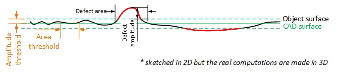
Illustration of the thresholds
SetAnomalyHysteresisYou can use the method
E3DComparer::SetAnomalyHysteresis.NET Python that is a more specific anomaly detection method.With this method, a cluster of points should have a large enough subset of its points with an even larger distance to the sample to be an anomaly.
This may be useful if you do not want to consider as an anomaly the points with a medium distance unless they are close to points with a high distance.
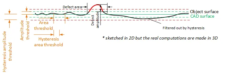
Illustration of the hysteresis thresholds
SetComparisonDistanceModeBy default, the aligned scan and the reference comparison is based on the euclidean distance between their corresponding points.
Use
E3DComparer::SetComparisonDistanceMode.NET Python with argument set toEComparisonDistanceMode_Euclideanto enable it.
Another possibility is to base the comparison on the angular distance between the corresponding normals of the scan and of the reference.
This works better to detect scratches.
Use
E3DComparer::SetComparisonDistanceMode.NET Python with argument set toEComparisonDistanceMode_Normalsto enable it.
There is a variant that is more robust towards false positives near the edges.
Use
E3DComparer::SetComparisonDistanceMode.NET Python with argument set toEComparisonDistanceMode_Normals_Advancedto enable it.
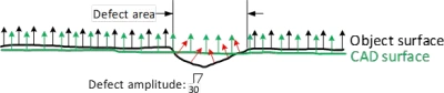
The Normals comparison mode
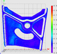 Scratch not visible using the euclidean distance mode.
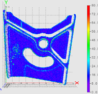 Scratch and false positives on the edges using the normals distance mode.
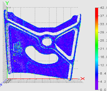 Only scratch detected using the advanced normals distance mode.
SetEnableAutomaticEdgeCropping and SetEdgeCroppingParametersSharp edges in the reference can lead to false positives, especially when using normals (see
E3DComparer::SetComparisonDistanceMode.NET Python). A solution is to remove them automatically:Use
E3DComparer::SetEnableAutomaticEdgeCropping.NET Python with argument set totrueto enable this.Use
E3DComparer::SetEdgeCroppingParameters.NET Python to adjust this function.By default, the edge cropping is disabled.
SetAutomaticCropFactorBy default, the sample clouds are automatically cropped around the reference plus a margin to avoid computing distance for points that are not on the object (for example, the plane on which the object lays).
The margin is obtained by multiplying the anomaly distance threshold by the automatic crop factor (set with
E3DComparer::SetAutomaticCropFactor.NET Python).By default, the factor is 1.
Note
If not called explicitly, the first call to Compare automatically computes the internal data structures.
Matching (Alignment and Comparison)
Base Case
Use the class E3DMatcher .NET Python to load a reference and a sample and to align and compare them at the same time.
E3DMatcher .NET Python inherits from E3DAligner .NET Python (see Alignment) and implements an API close to the one of E3DComparer .NET Python (see Comparison) with some extra capabilities due to the usage of the reference points of view used in E3DAligner .NET Python.
To use the E3DMatcher .NET Python:
The first step is to set the reference using the method
SetReference.In addition to the mesh or the cloud, this method also takes one or several
E3DPlane.NET Python or azimuth and elevation angles (see Calibration) for a definition of the azimuth and the elevation).The angles are used to compute the plane and are just an easier way to specify it.
Set the options of the comparison (ROIs, thresholds, mode…) and optionally a reference plane.
Call the
Matchmethod with the sample point cloud and its reference plane.Optionally, use
E3DMatcher::GetComparisonPointCloud.NET Python to retrieve anEPointCloud.NET Python that contains the distances.
You can perform all these steps interactively in the
Easy3DMatchMatchsample.The main difference between
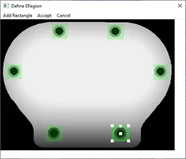
E3DMatcher.NET Python andE3DCompareris that the ROIs are defined usingERegion.NET Python on theEZMap.NET Python corresponding to the projection of the reference on the givenE3DPlane.NET Python.
This also allows for more advanced comparisons (see E3DMatcher::SetComparisonDistanceMode .NET Python and E3DMatcher::SetEnableMissingPointAsAnomaly .NET Python).
SetComparisonDistanceModeUse
E3DMatcher::SetComparisonDistanceMode.NET Python to select one of the methods available in the classE3DMatcher.NET Python to compute the distances:EComparisonDistanceMode_Euclidean_Fast.NET Python: the fastest method based on the euclidean distance between points. It is less precise on the edges.EComparisonDistanceMode_Euclidean.NET Python: the default method. It is based on the euclidean distance between corresponding points.EComparisonDistanceMode_Euclidean_Advanced.NET Python: the slowest method based on the euclidean distances. It penalizes more the bumps.EComparisonDistanceMode_Normals.NET Python: the same asEComparisonDistanceMode_Euclidean.NET Python except that the comparison is based on the angular distance between the points normals instead of the euclidean distance between the points. It works better to detect scratches.EComparisonDistanceMode_Normals_Advanced.NET Python: a variant ofEComparisonDistanceMode_Normals.NET Python that is more robust towards false positives near the edges.
SetEnableAutomaticEdgeCropping and SetEdgeCroppingParametersSharp edges in the reference can lead to false positives, especially when using normals (see
E3DMatcher::SetComparisonDistanceMode.NET Python).A solution is to remove them automatically:
Use
E3DMatcher::SetEnableAutomaticEdgeCropping.NET Python with parameter set totrueto enable this.Use
E3DMatcher::SetEdgeCroppingParameters.NET Python to adjust this function.By default, the edge cropping is disabled.
SetAllComparisonROIThe class
E3DMatcher.NET Python can perform the comparison on only a subset of the object. This has two benefits: it is faster and it allows to ignore false-positives when detecting anomalies.Use
E3DMatcher::SetAllComparisonROI.NET Python with one on severalERegion.NET Python to define the zones on which to perform a comparison.These
ERegion.NET Python should be interpreted as a masking part of the object on a projected view. UseE3DAligner::RetrieveReferencePoses.NET Python to retrieve the corresponding view.
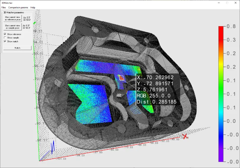
Only the areas on the ROI are compared
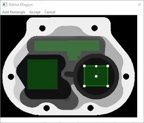
Illustration of setting ROI on a projection of the reference
SetAllComparisonNoExtraMaterialThe class
E3DMatcher.NET Python checks, for each point of the reference (in the ROI), the distance to its nearest neighbor in the sample.This avoids false positives, where we would use points of the sample that are not part of the object (the plane on which the object lays for example).
This allows to detect missing points on the sample.
A drawback of this approach is that extra material, that is points that should not be in the sample (for example, a hole that is filled) are not detected. You can solve this problem by specifying a list of
E3DBox.NET Python containing the areas that should not contain extra material.
We do not want the holes to be filled
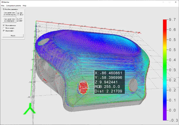
A filled hole is reported as an anomaly
SetEnableMissingPointAsAnomalyBy default, the points missing on the scan are considered as defaults.
In some case this may lead to false positives (a shadow on the sample is not necessarily a default, just the absence of information).
In other cases these points should be taken into account (for example, a deep hole in the object can result in the absence of points instead of the presence of misplaced points).
Use the method
E3DMatcher::SetEnableMissingPointAsAnomaly.NET Python to select one of these behaviors.
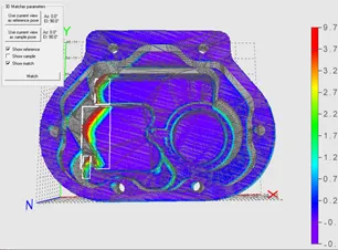
False anomalies due to shadows in the sample
SetAnomalyThresholdsAn anomaly is a sufficiently large contiguous area of points whose distance to the scan is above a threshold.
To specify the two thresholds (distance and area), use the method
E3DMatcher::SetAnomalyThresholds.NET Python.By default, these two thresholds are set relatively to the model size. To set the default values back, use the method
E3DMatcher::ResetAnomalyThresholds.NET Python.As a more advanced anomaly detection method, use
E3DMatcher::SetAnomalyHysteresis.NET Python.
Illustration of the thresholds
SetAnomalyHysteresisYou can use the method
E3DMatcher::SetAnomalyHysteresis.NET Python that is a more specific anomaly detection method.With this method, a cluster of points should have a large enough subset of its points with an even larger distance to the sample to be an anomaly.
This may be useful if you do not want to consider as an anomaly the points with a medium distance unless they are close to points with a high distance.
Illustration of the hysteresis thresholds
SetEnableAutomaticDecimationBy default, the clouds are automatically decimated in such a way that the decimation error does not impact the anomalies detection.
This has the benefit of speeding up processing.
If the resolution of your point clouds is small with respect to your distance threshold, calling
E3DMatcher::SetEnableAutomaticDecimation.NET Python with parameter set tofalsecould improve the speed as it will avoid useless decimation.
SetAutomaticCropFactorBy default, the sample clouds are automatically cropped around the reference plus a margin to avoid computing distance for points that are not on the object (for example, the plane on which the object lays).
The margin is obtained by multiplying the anomaly distance threshold by the automatic crop factor (set with
E3DMatcher::SetAutomaticCropFactor.NET Python).By default, the factor is 1.
Note
If not called explicitly, the first call to Compare automatically computes the internal data structures.
3D Sensor Fusion
3D sensor fusion is a technique to merge the output of different 3D sensors together. In this case, these are different views of the same object.
Use the class EPointCloudMerger .NET Python:
Choose how many sensors to use and position them.
Acquire scans of the calibration cube (that must be 3D printed).
Use the method
EPointCloudMerger::Calibrate.NET Python to perform the calibration.For each new object:
Acquire the scans of the object.
Use the method
EPointCloudMerger::Merge.NET Python to merge the scans together.
Hint
You can perform all these steps interactively in the C++ and C# Easy3DMatchPointCloudMerger samples.
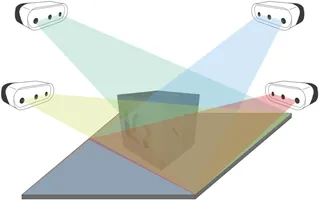
Several sensors acquiring different views of the calibration object
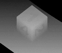
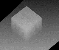
Scans of the calibration cube (displayed as ZMaps)
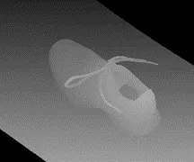
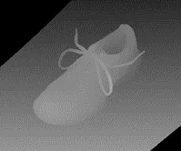
Scans of the object (displayed as ZMaps)
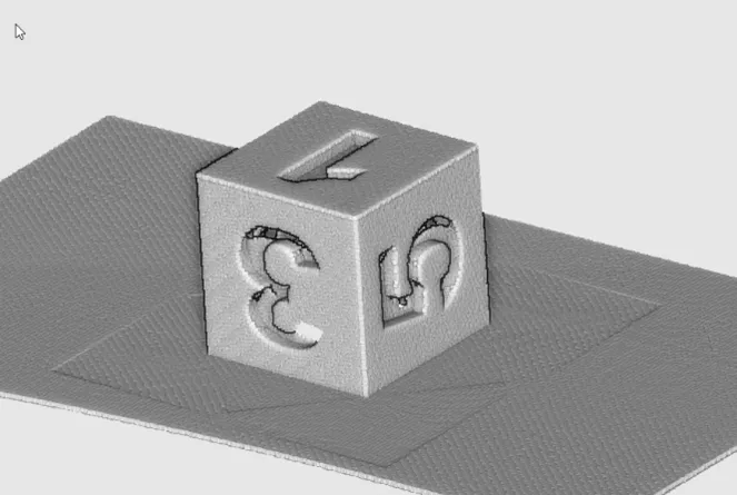
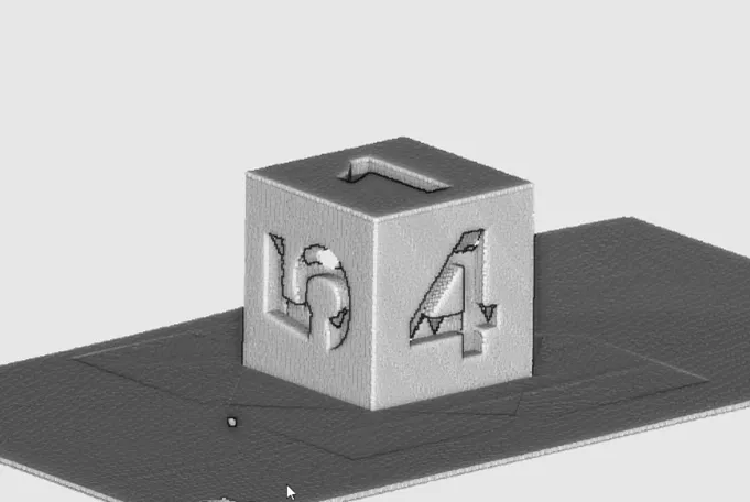
Merged calibration scans
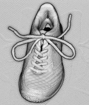
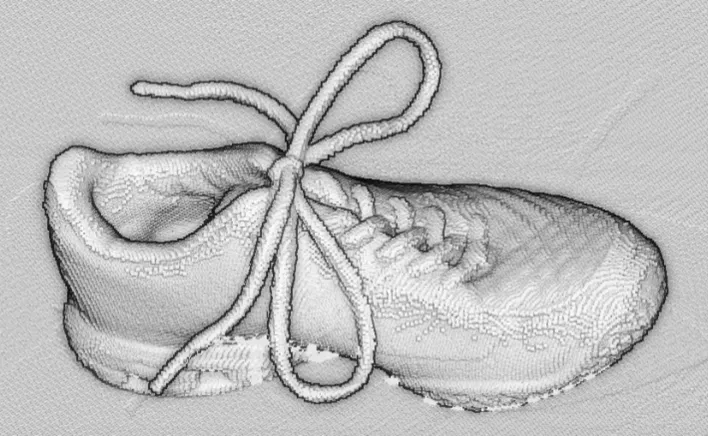
Merged cloud scans
3D CAD Model
The calibration cube model is available in the STL file format.
Download this file from the eVision download area in the
Additional Resourcessection (www.euresys.com/Support).
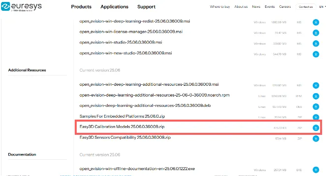
Download the calibration object model
Once downloaded, we recommend using a specialized subcontractor to print the 3D calibration cube as 3D filament printing is not really suitable to produce the cube.
For reference, we worked with a company using Selective Laser Sintering and printing a 10\(\times\)10\(\times\)10 cm cube using PA12 material costed 220 €.
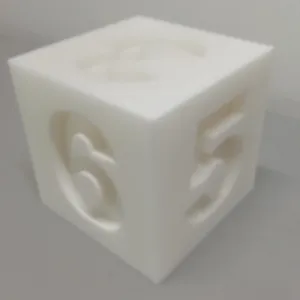
The calibration cube
Removing duplicate points
A physical point seen by two sensors should not be present two times in the output cloud.
By default, these points are removed. As this takes most of the processing time, you can disable the process if speed is an issue.
Set the cloud resolution with the parameter
EPointCloudMerger::SetMergedCloudResolution.NET Python to control this process. The parameter value is computed automatically but you can increase it to reduce the size of the output cloud and speed-up the processing.